
Learning output:
This module teaches all essential concepts, terminology and programming commands needed to operate a UR robot. The 8 modules are a step-by-step simulation of setting up and programming a complete pick-and-place application.
Collaborative robots vs. traditionally industry robots
Presentation of traditionally 6-axis industrial robots
According to Wikipedia, the first industrial robots came on the European market in 1973, it was the Swedish company ASEA today ABB and the German company KUKA who manufactured them. In the late 70s, Japan entered the market with FANUC Robotics.
The traditional industrial robot has since been widely used in industry to solve many different tasks.
For more information on robot history see:
Common to these robots are:
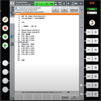
That the programming is text-based and not intuitive, for which a highly trained programmer and some training of the operator is required.
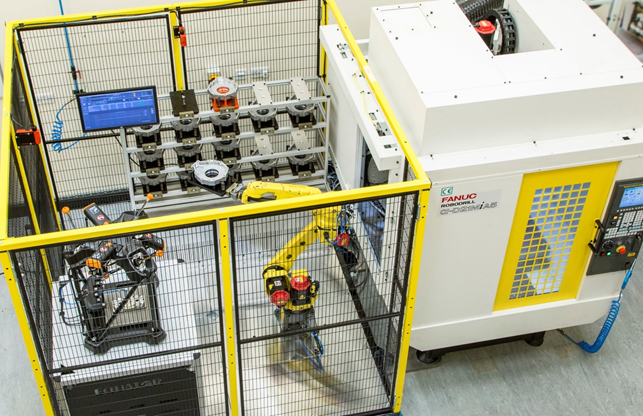
That they can cause serious damage to people as they can move very quickly, e.g. 11m/s (approx. 40km/h) with heavy loads, the largest KUKA has a payload of 1300kg
That they must always be placed behind a safety fence or secured against causing personal injury by other safety devices
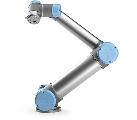
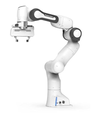
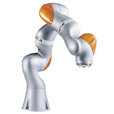
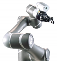
Presentation of Collaborative robots
Their vision was to create a robot that:
did not need fencing and advanced security solutions
was able to co-work side by side with people
was easy and intuitive to program, the machine operator should be the programmer
For security reasons, Cobots have the following features:
They have low movement speeds.
Limited payload UR 20kg, FANUC 25kg. Efforts are being made to move this limit up.
Force torque sensor ensure that they stop if they encounter resistance
They have no sharp edges that could injure a person
Their joints close together in a way that does not pose a danger of pinching the operator’s hands and body parts
Since 2008, a large number of robot manufacturers have developed their own version of a Cobot:
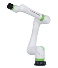
Today, the robot manufacturers are competing to develop the most intuitive programming solutions.
Control tasks 0: Collaborative robots vs. traditionally industry robots
Access to Universal Robots Academy:
The subsequent tasks must be completed here on the page and using the online training material, which is available on the universal website. Therefore, the first thing you need to do is to create an account on Universal robots academy.
Do this by following this link

What do Joints, Coordinate systems and I/O signals mean in relation to a UR Cobot?
The 6 Joints:
A 6-axis industrial robot as well as a Cobot have the following axes or joints.
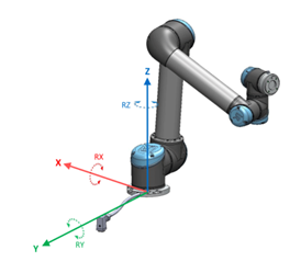
Coordinate systems:
A 6-axis industrial robot as well as a Cobot work according to different coordinate systems. On a UR-Cobot, they are named as in the picture. If you do not specify a specific coordinate system, all positions are saved as Base coordinates.
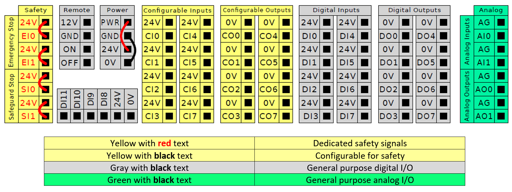
Input and output:
Most robots have the option of connecting to various inputs and outputs.
The UR robot has the following digital and analog inputs and outputs
You can use the horizontal Digital Inputs block (DI8-DI11), for quadrature encoding Conveyor Tracking
The meaning of the different colors must be observed
The configurable I/O can be configured as either safety-related I/O or general purpose I/O
Complete Module 1. FIRST LOOK: THE ROBOT AT A GLANCE
This module gives you a short introduction to the robot, user interface, I/Os and functions.
Control tasks 1: Joints, Coordinate systems and I/O signals
Complete Module 2. PREPARING A ROBOT TASK
In this module, you will prepare the robot for a pick-and-place task by connecting an end-effector, and by connecting and configuring sensors and conveyors.
Do et by fooling this link:
Control tasks2: Preparing a robot task
End effector or tool and their TCP
End effector and tool types:
When using a robot, an important part of it is the end effector or tool. It is the end effector that carries out the robot’s work tasks, e.g. moving and lifting an object.
These can be custom-made to fit exactly the item to be handled, or ready-made units can be purchased.
If a Cobot is to work alongside a human, without the use of a safety fence, it is important that the end effector has no sharp edges that could cause damage to the person.
Some work processes require end effectors with pointed ends. When these are used, extra attention must be paid to the risk assessment, a safety fence may be required.
TCP Tool Center Point:
To work correctly, all robots must know the location of the end effector Tool Center Point “TCP”.
If the robot does not know its tool’s TPC, the consequence is that linear movement cannot be performed correctly.
TCP is used to tell the robot how much the center point of the end effector, also called the tool, is offset in relation to the coordinate system located in its tool flange.
Tool Orientation:
Furthermore, in order to perform linear movements correctly, the Robot must also know where and how the Z+ on its tool is oriented in relation to the Z+ axis on its Base coordinate, which is the coordinate system that is placed in its foundation.
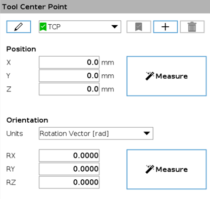
Specifying TCP and Tool Orientation:
You can tell the robot where its TCP is located and how the tool is oriented by entering position and orientation values directly on the teachpendant or you can use the robot to measure these values.
How the two methods are performed on a UR robot will be covered in UR online module 3
Payload and center of gravity:
To ensure that the robot can work optimally both when you move it manually in free-drive and when it executes the program you must specify how large a payload the robot has to lift and how much the center of gravity on the gripper is dislocated in relation to the flange coordinate.
Setting the payload correctly ensures optimal motion performance and avoids protective stops.
If the center of gravity on the gripper becomes very dislocated, it can result in a reduction in the weight the robot can lift.
It is possible to define multiple Payloads, and switch between them in your program. This is useful in Pick and Place applications, for example, where the robot picks up and releases an object.
You can enter Payloads and center of gravity values manually or you can let the robot measure them itself.
Complete Module 3. SETTING UP A TOOL
Learn how to find and configure the tool center point, how to teach tool orientation, and how to teach center of gravity and payload. In the end of the module, you will configure the gripper for the pick-and-place application that was prepared in module 2.
Do et by fooling this link:
Control tasks 3:
Motion types
MoveJ:
Is default motion on the robot.
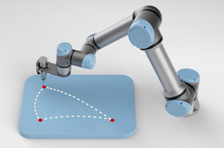
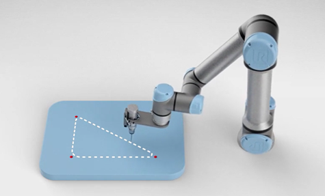
MoveJ is a non-linear movement, and may only be used where there is no danger of collision, for example from a point in free space to another point in free space. MoveJ is the robot’s fastest form of movement, and its trajectory depends on what the robot deems most optimal. This means that the path from one point to another can change if the speed changes.
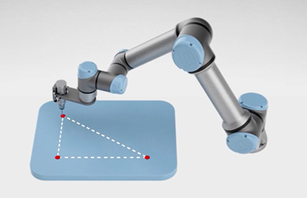
MoveL:
MoveL is a line movement type that moves the robot in a straight line between two points. MoveL must be used when, due to the risk of collision, precise movements from one point to another are needed.
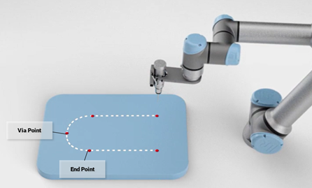
MoveP:
The moveP movement is like moveL but with a constant TPC speed. This is an advantage when welding or dispensing glue. To maintain its constant TCP speed, MoveP uses corner rounding. This is done by adding a blend radius to the positions.
Circle move:
When using MoveP, you can also program the robot to make circular movements.
Complete Module 4. CREATING A PROGRAM:
In this module you will learn about the robot’s different motion types, and you will program all the motions and waypoints needed for the pick-and-place application.
Control tasks 4:
Complete Module 5. INTERACTION WITH EXTERNAL DEVICES
In this module, you will learn how to operate the gripper, how to interact with sensors, and how to change the payload by using set and wait commands. Finally, you will program all the set and wait commands needed for the pick-and-place application.
Control tasks 5:
Complete Module 6. CONTROLLING CONVEYORS
In this module, you will learn how to control the conveyors by using a thread. And quite a few other fancy instructions 😊
Control tasks 6:
Complete Module 7. SAFETY SETTINGS
In this module, you will learn how to apply different safety settings to the pick-and-place application:
– How to trigger reduced mode using a safety scanner
– How to trigger a safeguard stop using a safety scanner
– How to connect and set up a safeguard reset button
– How to connect and set up an external emergency stop button
– How to define safety boundaries
– How to set up a tool sphere
Control tasks 7:
Complete Module 8. OPTIMIZING
In this module, you will learn how to optimize the pick-and-place application by adding blend radius to relevant waypoints, and by adjusting speed and acceleration.