
Micro unit: safety of cobots
(learning module 2: human and cobots co-working)
Description
Industrial robotic systems require safety requirements to protect people. These include, for example, safety fences, light barriers,…
In the case of cobots, robots and machines collaborate, so that extensive separating protective devices are not required, but the safety of persons must still be guaranteed.
But how can safety and accident prevention be guaranteed? In this unit, you will learn about safety concepts for cobots.
Duration: 1h
Keywords: Cobots, Safety, force and power limitation

learning output
I can…
…describe safety equpiments for roboter systems
….explain four types of collaboration
…explain the power and force limiation (PFL)
…name the safety requirements for installing and using a cobot
safety equipments for robotic systems
To minimize hazards in industrial robot systems, safety precautions are taken at a wide variety of levels.
- the immediate safety technology minimizes the risk as far as possible (e.g. increasing distances or changing the design).
- Indirect safety technology protects against remaining risks (light curtains, safety doors, ….).
- Indicative safety technology informs and warns users (e.g. signs).
The following safety functions are available today from most robot manufacturers:
- Safely reduced speed, e.g. monitoring
of the tool mounting flange when setting up at 250mm/s or during collaborative operation. - Safe Cartesian limitation of the movement space, e.g. to safely limit the movement range or to define a restricted space.
- Safe axis-specific limitation of the movement area, e.g. for safe limitation of the movement area or for defining a restricted area.
- Safely monitored standstill, e.g. by triggering of protective devices
- Safe brake ramps, e.g. for emergency stop, Enabling switch
Furthermore, the robot must be able to be used in different operating modes (e.g. set-up and programming), since work (e.g. maintenance, set-up,…) may also be required directly on the “naked” robot.
Operating mode T1: Manual reduced speed (for setup and programming). Here, protective devices may be opened and be ineffective.
Operating mode T2: Manual high speed (for testing the working speed). Here, protective devices may be opened and be ineffective.
A protected location for the setter is required. Furthermore, an inching circuit in connection with an enabling switch that the operator must press.
Operating mode: Automatic (for operational use)
The guards must be closed.
collaborative robotic systems
As with robotic systems, a risk assessment is required for collaborative robotic systems. In the case of cobots, the proximity between humans and robots must be taken into account in particular. Human-machine contact situations must be kept to a minimum.
Known collaboration types are
hand guidance:
If the robot is intended for hand guidance, a hand guidance device must be placed close to the end effector. This can be e.g. a force/torque sensor, whereby the robot can be manually guided similar to a manipulator can be manually guided. The robot must be operated at a safely reduced speed. In addition, an enabling switch and an emergency stop device must be provided within easy reach.
Speed and distance monitoring:
For speed and distance monitoring, non-separating protective devices are used so that persons can approach the robot at any time without being endangered.
Optical laser scanners or 3D cameras, for example, can be considered as protective devices. They must reliably detect the approach of persons and slow down or stop the robot movements accordingly. When the distance is increased, the robot continues its movement without acknowledgement. The speed must be safely monitored.
Safety-directed stop:
Safety-directed stop is a special case of speed and distance monitoring. When entering the collaboratioSafety-directed stop is a special case of speed and distance monitoring. Upon entering the collaboration space, the drives are immediately stopped and brought to a safe operating stop. When leaving the collaboration space, the robot continues its movement without acknowledgement. The level of speed is determined after risk assessment.
Force and or power limitation:
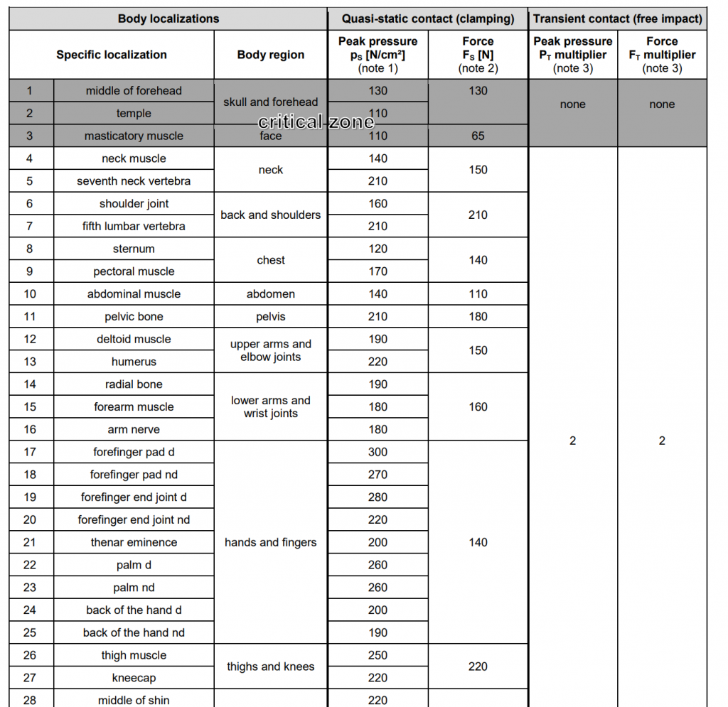
In general, it must be ensured that certain load parameters are not exceeded in the event of contact between the robot or tool and a person. biomechanical limit values must be considered differentiated according to body regions.
In order to minimize the pressure on the body regions, all edges of the robot system, including the tools, should always be rounded. One way of limiting contact forces is to apply protective devices directly to the robot and, if necessary, to the tool. Tactile guards are particularly suitable for this purpose. They trigger a stop upon contact with a person. A combination of tactile protective devices with capacitive or inductive protective devices is also possible.
efforts to safety systems for force and power limitation functions
Safe monitoring/limitation of torque: at the contact surfaces. Furthermore, all edges of the robot parts should be rounded.
Safe monitoring of speed: so that the required speeds are maintained and it is also ensured that a stop reaction occurs in an emergency.
Safe monitoring of position: so that certain body regions (such as neck or head) can be excluded or the assigned load limits can be defined.
Mode selector and enabling switches: are among the mandatory safety features of industrial robots. In the case of cobots, an enabling switch can be dispensed with if safety limits allow the various activities to be performed.
As part of the risk assessment, possible contact scenarios must be identified and the biomechanical loads (force and pressure) measured. Different limit values are specified for different body regions. The more sharp-edged the surfaces (e.g. tools), the higher the pressure. In addition to pressure, force must also always be taken into account. In the case of large and cushioned surfaces, the pressure is minimal, but too great a force could, for example, knock the operator over.
If the limit values are exceeded, the safety limits must be adjusted (e.g. reduction of speed).
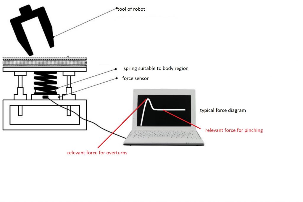
A measuring system can be used to determine the limit values. The most diverse body regions are simulated by means of springs with defined spring hardnesses.
A typical measurement result is shown in the figure.
For a pinching situation, the permanently occurring pinching force (see marked area) is decisive.
In the case of an impact, the maximum of the force curve.
In the meantime, there are also online tools (also in English) for the design of collaborative robot systems, such as the Cobotplaner. https://www.cobotplaner.de
Here, existing robot models can be loaded and the geometry of the tools used can be adapted.
Furthermore, the existing hazards and endangered body regions can be specified.
The tool determines the maximum speeds so that there is sufficient torque and force limitation.
Question Set: Check your knowledge
Checklist for installing a cobot system
Documentation
Are the following technical documents available for the robot application?
documents are available:
1.EC Declaration of Conformity
2.Risk assessment
3.Operating instructions CE mark
4. Proof of biomechanical limits
outer technical features
-Nameplate with name and address of the integrator
(Type plate of the robot is not sufficient)
-Emergency stop button easily accessible
-No sharp or pointed edges including tool and workpiece.
Tool and workpiece. Padding. Noshearing edges
-Can the employee remove himself from the
robot system or free himself at any time?
-Is the head outside the work area?Is the head outside the working area?
Is the robot safe?
Safe limitation of
Speed, position, force (category 3, PLd)?
inner safety
-Were speed, forces and pressures determined at the application to minimize the risk of injury (e.g. by minimize the risk of injury (e.g. by measurement)?