
micro unit 1:
communication techniques in smart factories
(module 1: digital twin for cyber physical factory)
Description
For producing automatically, flexible and efficient the ordered products with its individually parts or characteristics a perfect communication is needed.
For handling the orders the workpiece, the applications, machines and robots and even the manufacturing execution system (MES) have to communicate.
But how can they communicate among themselves?
Well, different communication techniques and interfaces has to be used. In this unit you will be informed about exemplary communication process and learn the used communication techniques for a successful production.
Duration: 1h
Keywords: RFID, PROFINET, MES, PLC
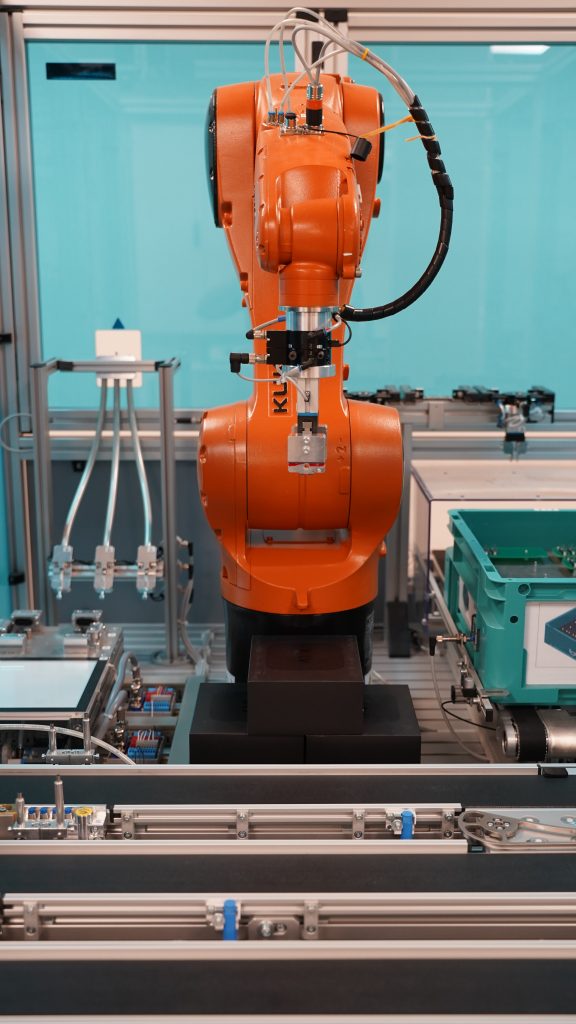 mounting application with robot for PCB green and fuses
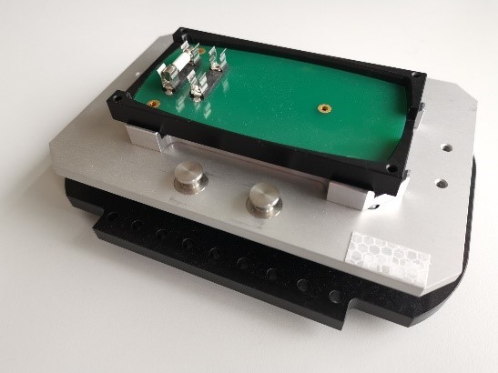 phone housing with PCB green and one fuse
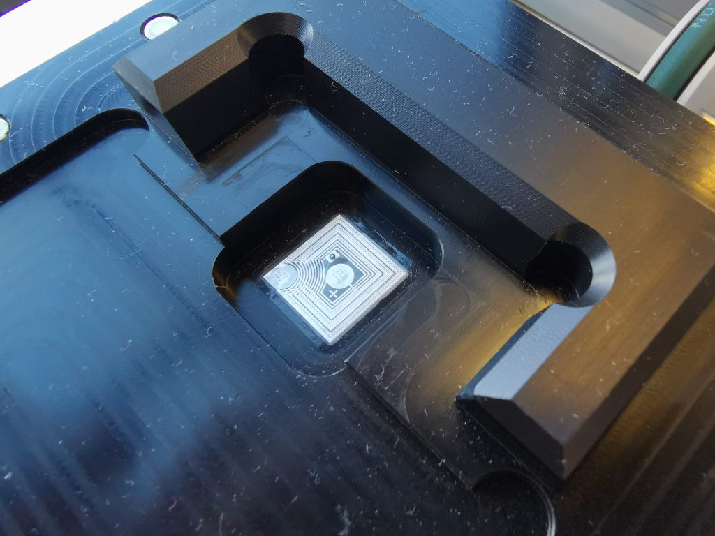
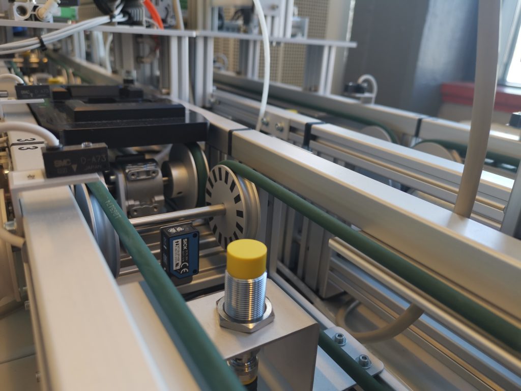
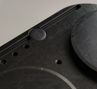 integrated RFID-chip at the bottom of the workpiece carrier
learning output
I can explain the communication technique RFID
I can desribe the used communication techniques for exemplary applications at different smart factories
I can compare the communication structure and describe their (dis)advantages
RFID technology for transfering data
(communication between workpiece, application and MES)
At an application it has to be decided if the workpiece has to be edited or if it can pass the application. Therefore the workpiece carriers owns a RFID chip with necessary saved data (see pictures). A RFID reader at the station reads then the saved informations from the RFID chip. In case of editing the workpiece, at the application, additional process parameters can be given to the application by saved data on the RFID chip .
After the editing at application new data has to be stored on the RFID chip (for the next application).
More informations about RFID in general:
RFID means Radio-Frequency Identification and can exchange data wireless between a transponder and a reader/writer device. The RFID reader/writer device is an active component, while the RFID transponder is passive. So the informations from the RFID-transporter can only be read or write if the transponder belongs to the emitted magnetic or electromagnetic field of the RFID reader/writer. The transponder consists of a microchip and a printed, laid or etched antenna. By induction princip a current is build up and with this energy the RFID transponder can be operated – even an own signal can be sent out. Next to the passive also excisting active transponder for transferring data to higher distances (till 100m). It can be stored usually data between 4 byte (for saving one unique number, unique ID: UID) and 8 kByte (for storing 4 typwriter pages) on a RFID chip.
The RFID transponder can interact with different frequencies. The higher the frequency, the higher the reachable distance. Low frequency (LF 125kHz) have low transmission rates and short transmission distances, the construction is easy and easy to handle. High frequency (HF 13,56MHz) have high transmission rates. The RFID antenna can be build smaller and simpler. Ultra High Frequency (UHF 860-950 MHz) systems have very high transmission rates and ranges. A dipol can be used instead of an antenna.
The passive transponder can be separated in 3 categories: Read-Only; Write-Once & Read Many (WORM), and Read & Write.
Read-Only: one-time writing data from producer, no possible to overwrite or change the data
Write-Once & Read Many (WORM): only one time writeable, data can not be changed afterwards
Read & Write: data can be written and read unlimited. It is possible to block for reading and writing.
Sources:
https://www.smart-tec.com/en/auto-id-world/rfid-technology
https://en.wikipedia.org/wiki/Radio-frequency_identification
RFID at phone housing factory
In this factory, on the RFID chip is not saved the whole production data, but the actual product state and the next application (resource) for operating. After executing the operation the next production step data is written with RFID on the chip. Hence, chips with lower storage space can be used (here having a space of 112 Byte).
In the MES mode on the RFID-chip is saved:
- the workpiece carrier ID
- the production order number (each order has its own number)
- the order position (if the order consists of multiple same products)
- the part number (each definied part has its own number – similar products can be differentiated)
- the resource ID (ID about the next application in production sequence, each application has its own resource ID)
- the operation number (information about the predefnied operation which will be executed)
exemplary screenshots of RFID informations at mounting station (Gb)
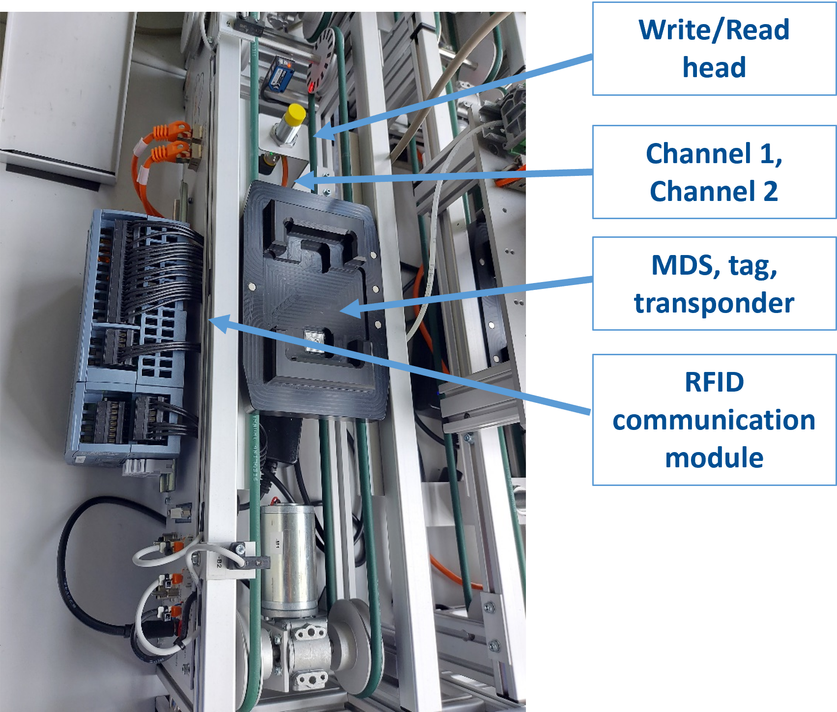
RFID at mystery box factory
Data can be written to and read from the transponder (TAG), which is mounted on the surface of the carrier. The read/write head unit is connected to the central unit via PROFINET. Communication is done by pulsed signals to avoid errors.
The software control of Turck RFID components is basically similar to the control of other I/O devices in the process, such as conveyors. However, there are certain things to consider when managing RFID components.
The user can perform read, write and other tasks using specific control outputs (outputs). It should be noted that the channels in use are dedicated to a specific function and have different input and output address spaces. The “Smart Factory” project has two channels, exclusively for writing and reading.
Online Quiz
check your knowledge about RFID and its use in Smart Factories
Processing of RFID data at the application
RFID at phone housing factory
When the workpiece reaches the application, the RFID chip data is queried. This data is passed on to the PLC via the reader. From there, the data is transmitted via Ethernet to the MES (Manufacturing Execution System) and checked for consistency. If the order data is correct, the MES releases the production and sends the data to the PLC of the application. The necessary production data originates here from the original RFID chip (operation number). The application carries out the processing. The PLC of the application controls the processing steps and gives further commands to a robot or machine if necessary. After completion of the operation, the PLC requests new RFID data from the MES. The MES sends the new or next production data to the RFID read/write device. The RFID chip is rewritten with information for the next application.
RFID at mystery box factory
Online Quiz
check your knowledge about the processing of RFID data
phone housing factory
communication between a machine and application
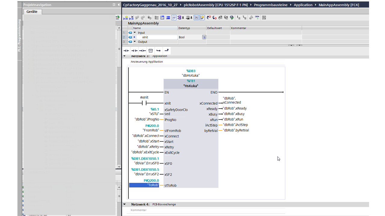
In the previous chapters you got an overview about the communication between workpiece, application and MES. At some stations we also have the usage of robots or e.g. milling machines. They have to interact with the PLC of the application.
Examplary application: fuse mounting station
Inform about the production process at the application “PCB and fuse mounting” (No. 5) and watch the video (click on the button below)
1. Depending on the order, there can be called 4 robot programs from PLC at this station. For each case exists one robot program (No fuse, top fuse, bottom fuse, both fuses). Additional, there’s a test program.
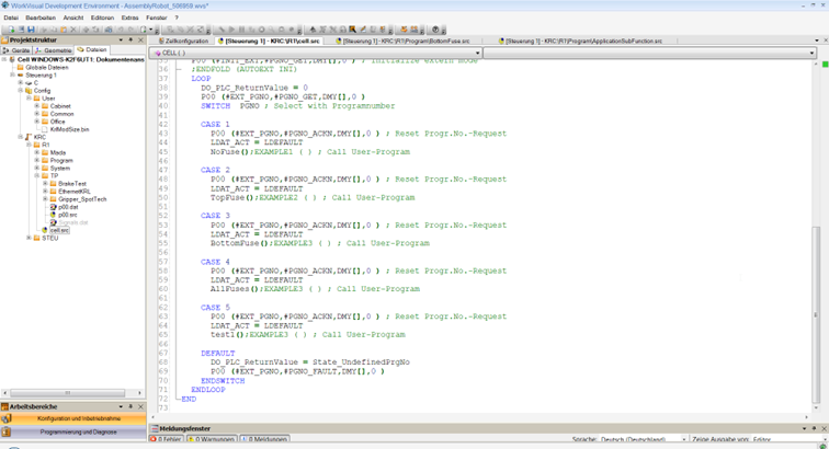
2. The information of the case number is transferred from MES to PLC. Therefore the PLC asks at MES and gets the robot program number. This number ist transferred then to robot (in the PLC-program the used input variable is “dbRob”.iProgNo)
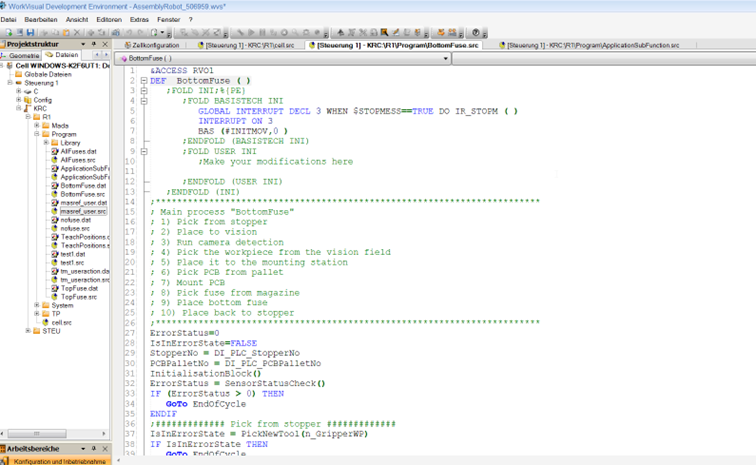
3. The robot program is then loaded and can start. The process for placing a bottom fuse consists of 10 steps (green comments at robot program)
4. The robot program is finished and gives a signal to PLC . The PLC asks now at MES for new data for workpiece carrier (RFID). Tgis data is written on the RFID-chip and the workpiece carrier can leave the fuse mounting station.
Exemplary application: bolt mounting station
Olease click this link to see a bolt mounting station